 |
|
|
|
|
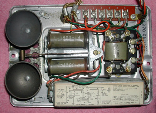 |
North H-Series Set Baseplate with Straight
Line Ringer. Note the flat plate at the end of the clapper arm (right end in photo) and screw head indicating the pivot point. The plate vibrates between the coil poles when ringing. Loudness is adjustable by increasing or decreasing the gong spacing. "A unique magnetic air gap bias uses the magnetic circuit of the ringer to secure the biasing effect and eliminates the use of springs or strings. This ensures a fixed and permanent adjustment for the life of the ringer. The bias prevents the tapping of bells during dialing." |
||||||||||||||||||||||||||||||||||||||||||||||||||||||||||||||||||||||||||||||||||||||||||||||||||||||||||||||||||||
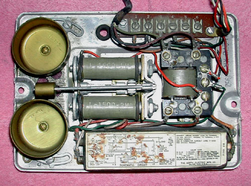 |
North H-Series Set Baseplate with
16 2/3 or 16 Hz Ringer.
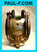
Frequency-Tuned Ringers are identified by the weight shape and stiff spring attaching the clapper arm to the ringer base. They are also marked with model number and frequency on the surface facing the gongs, like the one below for a 66 cycle (now 66 Hz) ringer. 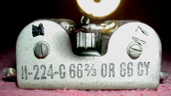 |
||||||||||||||||||||||||||||||||||||||||||||||||||||||||||||||||||||||||||||||||||||||||||||||||||||||||||||||||||||
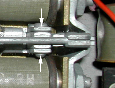 |
The clapper arm attachment point for
frequency-tuned ringers is shown by the arrows. It is not at the
end of the clapper arm as might be expected. Therefore the end of the clapper arm (right end in the photo) vibrates in the air gap between the pole pieces. The rate of vibration is influenced by: 1. Electrical factors: the ring frequency supplied by the line, the total coil resistance (of the two coils in series), and the series capacitor value, and 2. Mechanical Factors: the spring stiffness and the weight's mass and location on the clapper arm. |
||||||||||||||||||||||||||||||||||||||||||||||||||||||||||||||||||||||||||||||||||||||||||||||||||||||||||||||||||||
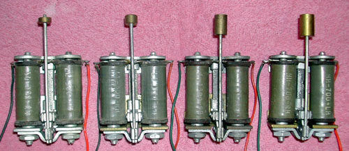 Frequencies (Hz): 66 2/3 / 66 54 30 25 The circuit is tuned both mechanically and electrically to respond to the desired ringing frequency while rejecting other frequencies. Clapper size and weight increase as frequency decreases. Spring stiffness decreases as frequency decreases. Appropriate coil resistance and capacitor sizes are shown in the following tables from the catalog. |
|||||||||||||||||||||||||||||||||||||||||||||||||||||||||||||||||||||||||||||||||||||||||||||||||||||||||||||||||||||
|
STANDARD
IMPEDANCE RINGERS
|
HIGH IMPEDANCE
RINGERS
|
||||||||||||||||||||||||||||||||||||||||||||||||||||||||||||||||||||||||||||||||||||||||||||||||||||||||||||||||||||

|
©2009 paulf. All rights reserved.
|