 |
|
|
|
|
 AW photo
Photos marked "AW photo" on this page were supplied by Alan Wallace in 2008. Edited and used with permission. |
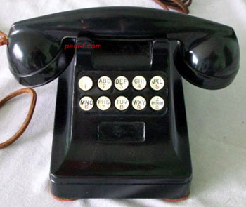
Overview Built in a 302-style case with F1 handset. Two rows of 5 keys on the front plucked reeds to produce two tones for each digit using a two out of five frequencies code. Based on a design tested at Bell Labs in 1941 and put on the shelf during World War II. The same tones were used between phone company offices for signaling and supervisory functions. "The plucked reeds were found not to be stable and rugged enough to maintain adjustment with constant usage in a station environment."* After the transistor was developed, research turned to electronic oscillator designs. * A History of Engineering and Science in the Bell System, Switching Technology (1925-1975), page 166. |
 |
|
 Set in the
JKL
Museum
|
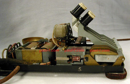
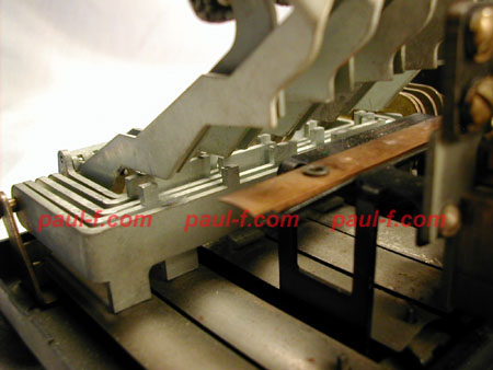
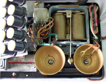
Side
view
shows the key linkage and a metal reed, surrounded by a
coil.
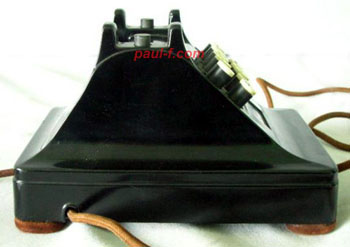
There are five reeds in a line behind the visible reed. Force from each keystroke is transferred to the five brass fingers in the right foreground. Each plucks one reed. This linkage is a mechanical work of art. Note the handset cord exits through a hole in the lip of the base. |
 Set in the
JKL
Museum
|
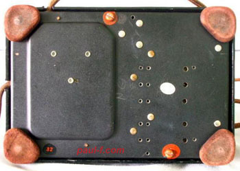
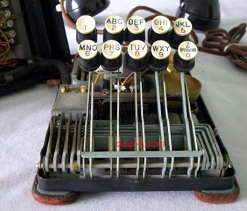
Tabs on the horizontal bars
select which two of the five reeds are plucked when a key
is pressed.
(Reeds numbered left to right, viewed from the front of
the set.) Key Reeds Plucked 1 1 2 2 1 3 3 2 3 4 1 4 5 2 4 6 3 4 7 1 5 8 2 5 9 3 5 0 4 5 The metal bar on "stilts" stops the downward motion of the keys. The arched metal strips on the bottom are springs that return the tabbed bars to their normal position when the key is released. |
 Set in the JKL Museum |
Position of the
"fingers"
when a button is pushed and a reed is plucked. When the fingers retract, the reed vibrates in the magnetic field of the large magnet, inducing the signal in the coil. The signal can be heard in the handset - even if the phone is disconnected from the line. Click below to hear the set dial the indicated sequence: (You may need to hit your Browser "back" button to return here.) (If you hold down the Shift key while clicking, the tones may play in another window.) 1 2 3 4 5 6 7 8 9 0 9 7 8 - 5 5 5 - 1 2 1 2 Thanks to Steph Kerman for noise and size reduction processing on these sound files. See Phil's video of this set on YouTube: https://youtu.be/wg2M9suLXHA |
 |
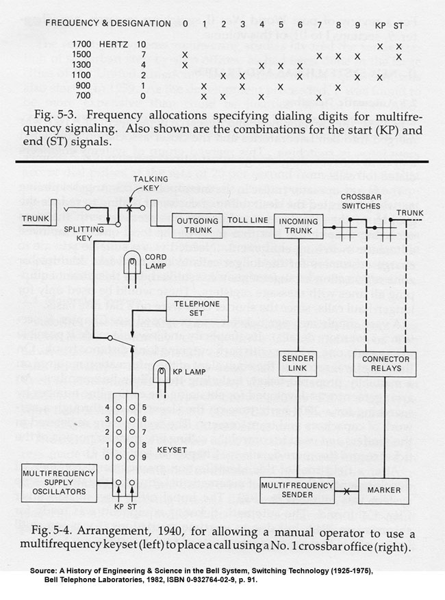
Steph Kerman analyzed the recorded tones for each button push and identified the frequencies produced by each reed as follows: Reed Frequency Designation* 1 700 Hz 0 2 900 Hz 1 3 1100 Hz 2 4 1300 Hz 4 5 1500 Hz 7 * From table 5.3 below. We can clearly see in his charts the peaks for each of the two tones produced for each button push. These are the same "multifrequency" (MF) tones that had been used for years to send supervisory and pulsing signals in switching applications. Origin of MF Tones The frequencies and combinations were developed after field trials in the 1930s. The frequencies chosen were in the voice band, partially to ensure their transmission in limited bandwidth (long distance) situations. To avoid false signals triggered by voice conversations among operators, a "KP" start tone and "ST" end tone were added to the 10 digit tones. This clarified when the receiver hardware should expect valid tones and also permitted the transmission of variable length messages. A 1940 trial in Baltimore led to more general use in switchboards starting in Philadelphia in 1943. Development and implementation was obviously impacted by World War II. 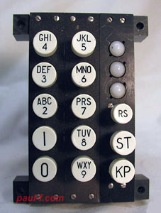 The Field Trial set needs only 5 reeds The switchboard MF dials needed 12 pushbuttons (10 digits, KP and ST), requiring using a two of six code to transmit codes for all the buttons. Since the field trial pushbutton set only produces the digits 0 through 9, the 1700 Hz tone is not needed. Thus, the set contains five reeds instead of six. (Fig. 5-3 below.) In Fig. 5-4, we see that the operator's set was supplied with tones by "Multifrequency Supply Oscillators" that served the entire CO. Since these were not available in homes, the tuned reeds were used as a mechanical means to produce the tones. Ingenious. |
 |
|
 AW photo |
 AW photo As shown, the keys flop from side to side on the long arms fixed only at the bottom. In use, the thick metal housing holds the top end in place. The housing hole for each key is slightly elongated to allow for the movement of a cylinder at the end of each arm. |
 Set in the Lucent Archives |
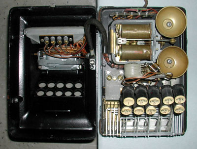
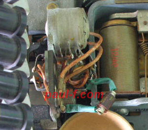
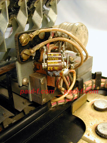
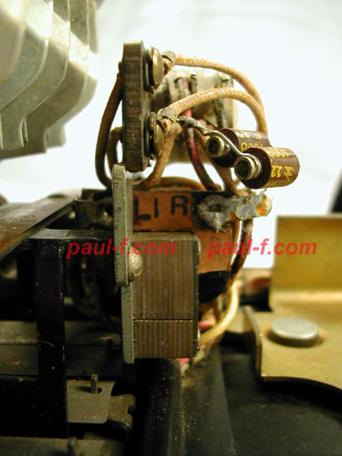
Inside views (here,
above and
below) show the network just behind the buttons and
capacitor tucked in
the housing near the switchhook. Cabling is elegantly done, with a 5 position terminal strip behind the ringer to accommodate the mounting cord attachment. |
 AW photo |
Fortunately,
the
transistor was
invented in 1947 and provided a better
development path toward pushbutton dialing. It took several years to develop low cost reliable transistorized oscillators to enable the production of the modern DTMF "Touch Tone" dial. To continue on the evolutionary path of pushbutton dialing, click here. |
 Set in the JKL Museum |
 Set in the JKL Museum |