WE Experimental
Data Phone Card Readers
|
| (What's
this copyright notice?) |
|
|
|
| On this page: Card Reader '59 Keyset Card
Reader '62 '66
Uses Data Phones '60s |
 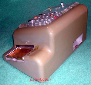 |
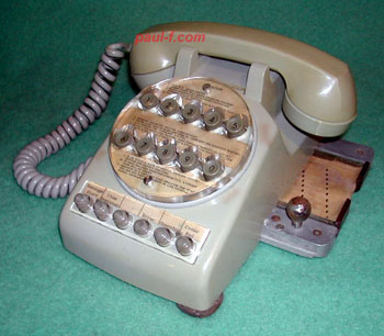
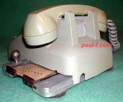
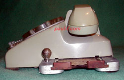
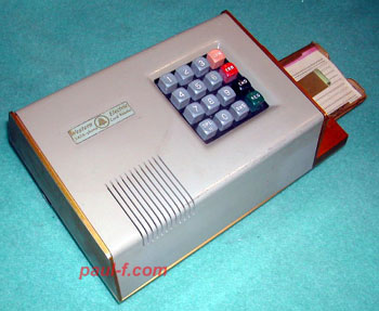
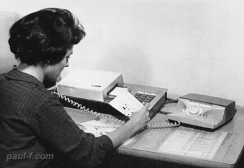
Data Phone Card Reader ca. 1959 The Data Phone Subset plugged into the back of the reader, and provided the connection to the phone line. Each button push or row sensor on the card reader produced 2 contact closures, that were converted by the subset to 2 audio tones. A speaker with volume control provided feedback from the other end of the connection. A seperate 502 set (single line with exclusion) was used to dial and provide a voice link. Cards were placed in the carrier on the right and pushed in when ready to transmit. Each column would be read as the card carrier returned to its original position. Pre-punched cards contained codes for operator identification, destination and item description. Quantities desired were entered via the keyboard. Trials were held in New York and Illinois. Card readers in the Operating Companies were used to place orders. The receiving end at the distribution centers had a more complex subset that converted the multi frequency tones to contact closures, which controlled an IBM model 024 card punch. Cards punched were then read into the distribution center's computer system. Sources: "Proposed Western Electric Company Arrangement for Mechanized Ordering Using Dataphone Service," AT&T, January 19, 1959 "Data Input Equipment Designed for Distributing House Operations," The Engineer, Western Electric, January 1959, page 18. (Field test announcement: Bell Laboratories Record, August 1959, page 314) https://www.telephonecollectors.info/index.php/search?q=blr+dataphone+card+reader |
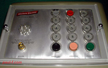 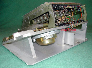 |
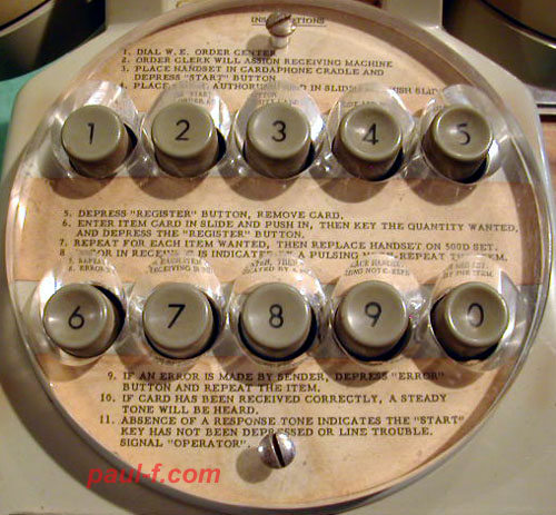
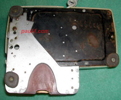
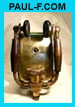
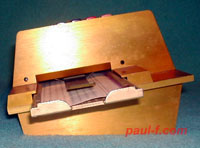
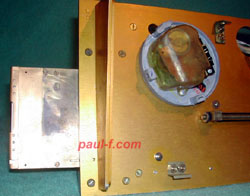
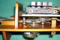
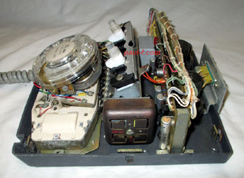
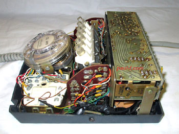
Keys labeled as follows: Special Error 0 1 2 3 4 5 6 7 8 9 Order End Operator Register 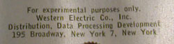 The card carriage is connected by a gear train to a standard 7D dial. When the carriage is pushed in, the dial's spring is wound up. When released, the dial spring pushes the carriage out at a rate determined by the dial's governor. No external power is required. Look at the thickness of that metal frame! This design was shared with about 35 office machine makers. Western Electric was looking for someone to make the units and did not want to be perceived as competing with the office machine makers. The units do not have any model numbers or dates stamped in ink as most experimental or field trial sets do. |
 |
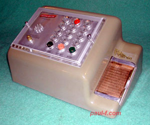
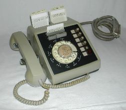
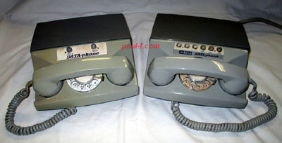
Data Phone Card Reader ca. 1962  Simplified design and more streamlined packaging. Capacity was increased to be able to hold a standard 80-column data processing card. Bell Laboratories Record, March 1962, page 74."A Low speed Data Set for High speed Business" by R. Sokoler. https://www.telephonecollectors.info/index.php/search?q=blr+low-speed+data+set |
   |
This model has a similar
heavy metal frame and uses a standard dial to push the card
past the reading fingers. The button array is more
compact and integrated. Button legends are: 1 2 3 OPR 4 5 6 ERR 7 8 9 END SPL 0 DNS REG |
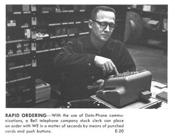 |
Uses By January, 1964, the system was rolled out to several other distribution centers, including Arlington, VA. This photo is from the Illinois Distribution Center installation. The Dataphone subset can be seen plugged into the back of the card reader. (Western Electric News Features, January 1964. Scan courtesy of Wayne Merit.) |
 |
Starting around 1961, the
system also used Card Dialers for data input. Ordering info and item part numbers were stored on plastic cards. Quantities were entered using the phone's dial. Several BLR articles mentioned the use of card dialers in financial applications, and show the specialized cards used. https://www.telephonecollectors.info/index.php/search?q=blr+card+dialer For Card Dialers, go here. |
 |
Data Phone Card Reader ca. 1966 This later model was used in Tempe, AZ in an integrated data processing system that linked all schools in the Elementary School District. The card reader was packaged as a separate unit. A general purpose, production Data Phone was used. (Bell Telephone Magazine, spring 1966, Scan courtesy of Jeremy Walters.) |
 |
Data phones Examples of production sets (without card readers) 401E (1963) - transmitter (one way), 20 characters per second 804A (1969) - "up to" 1200 bits per second (1960's Bell System DATA-phone, Data Set Commercials) https://www.youtube.com/watch?v=QsqHBzW6gS0 |
 |
Data Phone 401E internals Uses Princess components -- dial, network and hookswitch. Note: There is a marketing brochure for the 401E in the TCI Library. |
 |
Data Phone 804A internals Higher speed. Tight fit! |
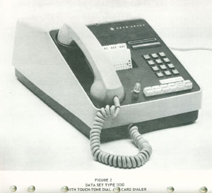 |
Data Set 103G Western Electric eventually made a Data Set with integrated Card Dialer. I'd like to find one, or at least a good photo. For Card Dialers, go here. |